
Payload Computer (PLOC)
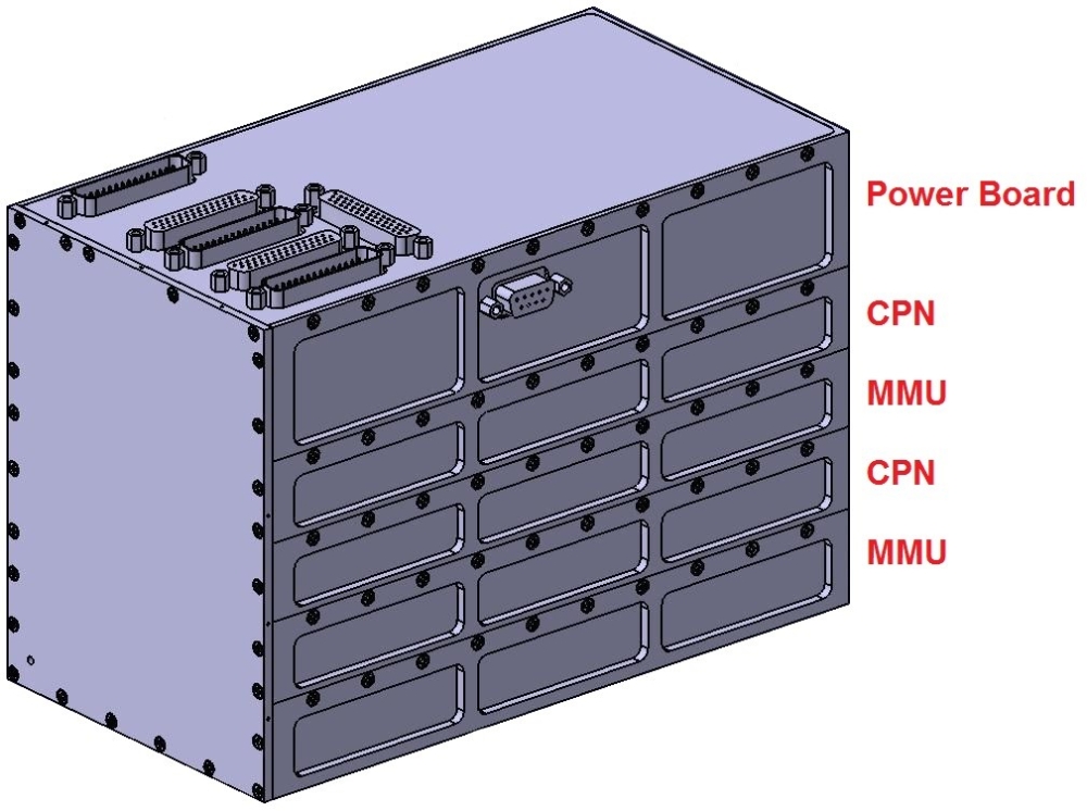
For payload control as well as for the management of the payload data, Flying Laptop is using a dedicated Payload On-board Computer (PLOC). The heart of this computer is a Virtex-II-Pro FPGA from Xilinx. It is built into a board, the central processing node (CPN), which was developed and build by the Fraunhofer Institute for computer architecture and software engineering. The use of this FPGA leads to a high parallisation, which is necessary for a simultaneous control of different payloads and for receiving payload data simultaneously. CPN also has another smaller FPGA, the Spartan 2, for its own management. This FPGA is responsible for the CPN itself and, therefore, not only sends housekeeping data but also configures the main FPGA. For the second task, it has access to three flash chips to save configuration files on them. The usage of a second FPGA allows being able to program the main FPGA even after launch. In addition to the FPGAs, the CPN also has elements for intermediate storage of payload data. For this task, it has three DDR SDRAM chips with each having a capacity of 128MB. In addition, it has access to four SSRAM chips with 4.5MB each. Beside these main features, CPN has even more features like a comparator for current monitoring, an EEPROM and a NAND flash. CPN not only is responsible for the payload itself but also for the Mass Memory Unit (MMU). This unit is used for saving payload data. Using the MMU CPN has access to 2GB flash memory. The MMU was developed, build, tested and programmed at the Institute of Space Systems. The core of the MMU is a ProASIC3L FPGA from Actel. The combination of CPN and MMU is a complete unit for payload control. Because of redundancy there are two such units implemented in PLOC.
The PLOC's electronic is completed with the Power Board. This board was also developed, built and tested at the Institute for Space Systems. The tasks of this board is primarily to convert the bus voltage to a lower voltage. However, it also controls the startup procedure and the emergency shutdown.
Multi-spectral Imaging Camera System (MICS)
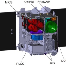
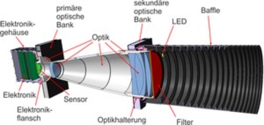
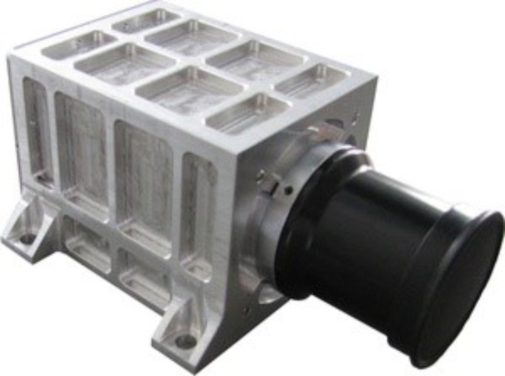
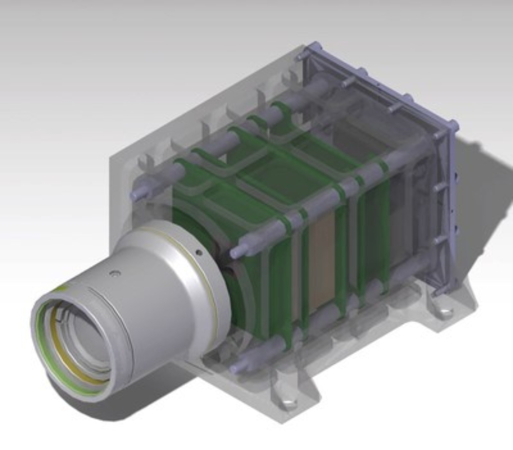
The Multi-spectral Imaging Camera System (MICS) instrument will be the main imaging payload on the Flying Laptop. It is designed for two purposes. The main purpose is Earth observation of specific targets from multiple angles, which may be used to determine the bidirectional reflectance distribution function (BRDF). In a second application, MICS is used for Earth observation in the nadir-pointing mode, as well as in the target-pointing mode. Among other things, this can be used for the in-orbit verification of the AIS receiver system on board the satellite. Since the first application is more ambitious MICS is designed for multi-angle Earth observation, fulfilling the second application in the best possible manner. MICS is designed as matrix scanner with the spectral channels red, green and near-infrared. The major requirement for the multi-angular Earth observation is a good signal-to-noise ratio (SNR), while a particularly high ground sample distance (GSD) is not mandatory. As a result, the system has a GSD of 21.5 m for an orbit altitude of 600 km. The corresponding swath width is 22 km. The system consists of three separate cameras aligned on an optical bench in a triangular position (see figure above). Each camera has an identical design including the optic. The only difference are the filters used and - resulting from the chromatic aberration - the exact position of the focal plane. MICS has been designed around the CCD interline sensor Kodak KAI-1003M. Each camera consists of nine main components (see figure below). First the electronics housing, the read-out electronics, the CCD sensor including the sensor board, the electronics flange, the optics, the optics brackets, the filter, the baffle and at last the on-board calibration system. The optics frame is made of titanium to allow for minimal thermal expansion. Materials not sensitive to the radiation environment in orbit are selected for lenses and filters. The Payload On-Board Computer (PLOC) handles camera control, data processing and data storage. MICS is mounted on an optical bench to minimize misalignment between the cameras due to thermal expansion. The optical bench is made of an aluminum sandwich structure with carbon fiber reinforced plastic as cover plates. The star trackers are mounted on the same bench for highly accurate pointing information.
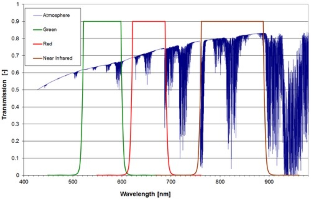
The filters are designed for scientific earth observation purposes. Thus, the definition of the channels is strongly driven by the atmospheric absorption, as illustrated below, which shows the defined spectral channels and the absorption of the atmosphere. In addition to a preferably high transmission within the channels, the filters must block the radiation within the sensor sensible spectrum between 200 nm - 1000 nm. To characterize and calibrate the cameras in the laboratory, an optical test facility was established in a shaded area of the integration room. Details can be found here. Each camera is equipped with a newly developed LED calibration system to detect possible degradation of the sensor or the optics in orbit.
Panoramic Camera (PAMCAM)
The narrow field-of-views of the scientific camera system MICS enforce the request for an additional camera system capable to provide an overview of the observed landscape. The so-called Panoramic Camera (PAMCAM) should be able to take color images in order to increase the public outreach of the Small Satellite Program. During MICS operations, the PAMCAM will be used simultaneously but with a reduced capture frequency. The figures below show the CAD model and the EQM of PAMCAM. The camera system has a mass of 400 g and dimensions of 126 x 78 x 58 mm³. These values include housing, electronics and optics.
PAMCAM is based on the COTS-camera BCi5-LS-B-40 manufactured by C-Cam Technologies, which is a division of Vector International. The generic electronics has been modified and supplemented with an interface board and a power board developed at IRS. The power consumption of the camera is below 2 W. The camera is equipped with the IBIS5A-1300 CMOS sensor designed by FillFactory. It has 1280 by 1024 pixels with a pixel pitch of 6.7 μm and features a Bayer RGB color pattern. The digitalization is conducted with 10 bits and image data is transmitted as raw data. The lens MEVIS-CF 2516 from Qioptiq has been modified to withstand high mechanical loads and was integrated into the camera. It has a focal length of 25 mm and an f-number of 1.6. PAMCAM can cover a field-of-view of approximately 20°x16°. This results in a swath width of 200 km and a ground sample distance of around 160 m from a 600 km orbit. The SNR has been conservatively calculated to be above 100 for land cover targets under daylight condition.
The Payload On-Board Computer PLOC conducts camera control and data reception. The data interface consists of seven LVDS lines, where six are used to transmit the image data and one for controlling the camera. The camera has been qualified with a combined thermal-vacuum-cycling test according to ECSS standards for an operation within a temperature range of -10°C to 40°C. Non-operating temperature range is -20°C to 65°C. The camera also passed the mechanical qualification with 20 gRMS.
Data Downlink System (DDS)
The DDS (Data Downlink System) is a system, which sends the payload data to a ground station. It sends the pictures with a rate of 10 Mbps to the IRS ground station in order to be able to transmit the required amount of data in the limited transmission time. HAM amateur radio frequencies are used within the S-Band.
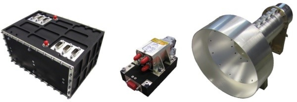
In order to do so, three pieces of equipment are used:
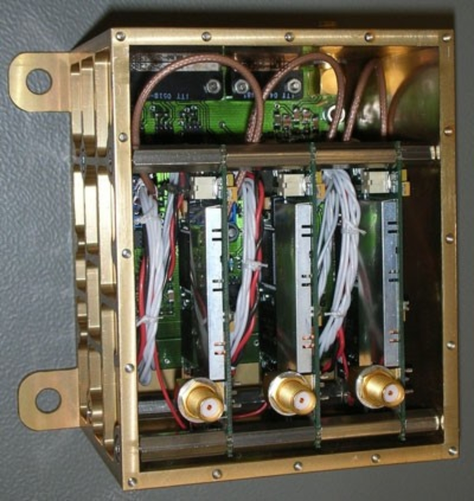
- Two redundant transmitters (on the left) modulate the signal into a SRRC (Square Root Raised Cosine Filter) QPSK (Quadrature Phase Shift Keying) waveform. The output power of the transmitter is about 0,5 Watt. The transmitter has been developed with COTS components and qualified at the IRS.
- A space qualified switch (center) is used to switch between the two transmitters in case one of them fails.
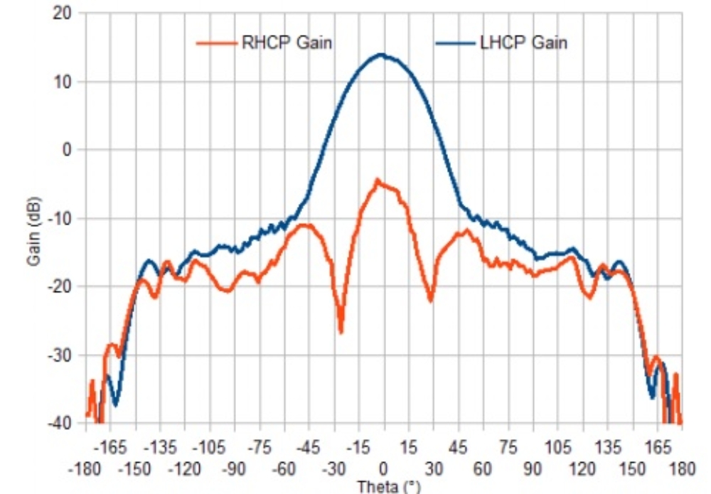
- Finally, an antenna (on the right) is used to transmit the signal into free space. This antenna has a gain of about 13,5 dB and is circular polarized in order to minimize the influence of the orientation and position of the satellite on the link budget. The antenna is based on waveguide technology and was developed at the IRS.
Optical HighSpeed Infrared Link System (OSIRIS)
The Optical HighSpeed Infrared Link System (OSIRIS) is a technology demonstrator developed and built by the Institute of Communications and Navigation of DLR at Oberpfaffenhofen. Its goal is the demonstration of a cost-efficient optical downlink system with low technical complexity, which can be used on future small satellite missions.
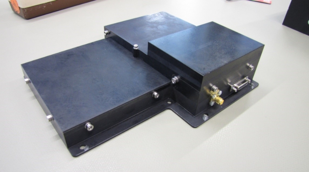
The instrument consists of two different optical transmitter units, which are integrated into a single housing. Each unit is connected to an external collimator by fibre optics. The collimators will be mounted on the optical bench to ensure an ideal alignment with the payload cameras and the satellite's z-axis. The supply voltages needed by the transmitters are generated inside a separate box.
The two transmitters use different technologies. One is based on a high power laser diode while the other comprises a laser module and an erbium doped fiber amplifier (EDFA). Both transmitter units work at a wavelength of 1550 nm and use on off keying as modulation. OSIRIS has a maximum power consumption of 25 W and a mass of about 1.5 kg. The maximum transmission rate from orbit will be 80 Mbit/s.
AIS Receiver
In the third quarter of 2012, Flying Laptop got an AIS receiver including an antenna as a new payload. This payload was developed, built and tested by the DLR Institute of Space Systems in Bremen. This system can receive AIS signals from ships. Before continuing with the introduction of the payload, we would like to introduce the AIS system itself. Since January 1 2004, it has been mandatory for all ships bigger than 300 GRT to run an AIS transmitter in international waters. Since July 1st 2008, all ships in national waters bigger than 500 GRT also need to run an AIS transmitter. The Automatic Identification System, AIS, is a system designed to supervise marine traffic. In times of increasing ship traffic, a system like this is indispensable. AIS shall be used for the following:
- Preventing collisions
- Providing information about ships and their cargo to adjoining coastal states
- Serving as an appliance for landside surveillance
The system works as follows:
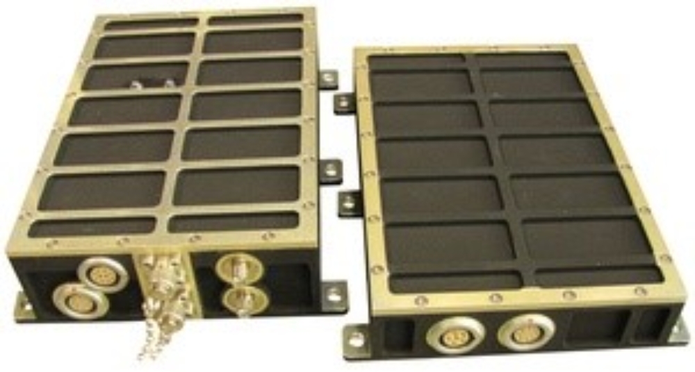
Ships will send messages in regular time intervals. Among other data, these messages contain position, route, and velocity of the ship, the ship name and the call sign. If a ship has an AIS receiver on board it can use the signals for better planning and decision-making. These AIS signals can also be received from space. In a last-minute cooperation between DLR and the Institute of Space Systems of the University of Stuttgart, an AIS receiver including an antenna could be accommodated within the satellite. According to the slogan "form follows function" the unusual form of the AIS receiver housing was created.
Other satellites are already recording AIS data and tracking the route of ships. The novelty with Flying Laptop is that few satellites have both an AIS receiver and a camera system onboard. This created the possibility of checking how strongly the system is used and how well the received signals correspond with the real position of the ships.
GENIUS
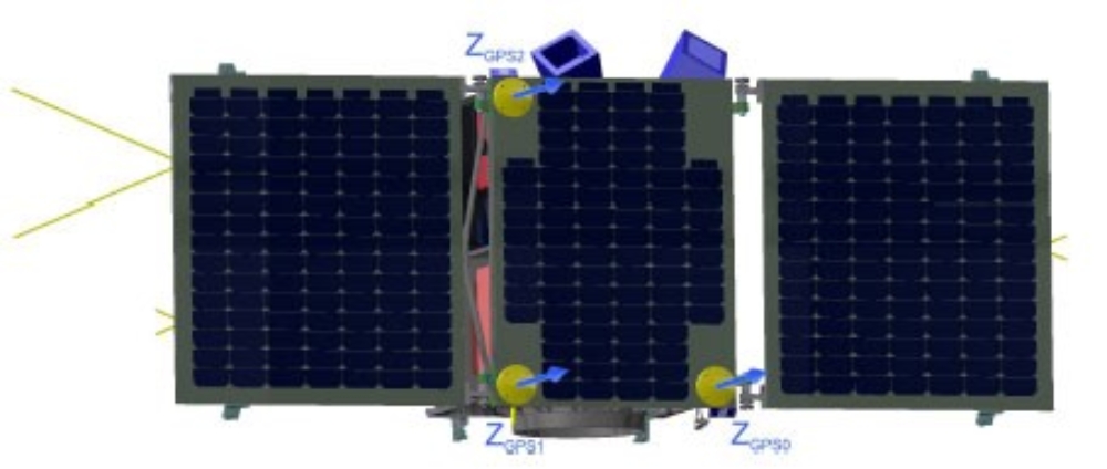
GENIUS, the "GPS Enhanced NavIgation system for the University of Stuttgart micro-satellite", is developed in cooperation with the German Space Operations Center in Oberpfaffenhofen, Germany. The antennas of the three independent GPS receivers are mounted in the corners of the center solar panel in an L-like configuration. The GPS system provides real-time data about position, velocity and time with an accuracy of up to 10 m, 0.1 m/s and 1 µs. New about the GENIUS experiment is the crystal oscillator, which provides a stable reference frequency and keeps the GPS receivers in sync. In addition, raw data and carrier signal measurements will be dumped during ground station contacts for further processing. Using those measurements, it will be possible to determine the Orbit with an accuracy of up to 1 m. Furthermore, it will be possible to determine the attitude of the satellite with an accuracy between 0.1° and 1°.
pLayload
Welcome to Massive Multiplayer Online Spacecraft Operations!
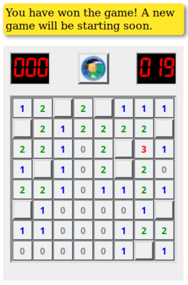
You can take part in checking @Flying_Laptops memory for Memory Inconsistencies Nursed by Energetic Signals (MINES). Flying Laptops memory is divided into 64 block of memory. Some math and a lot of guessing showed that in each block there could only be one MINES maximum. In addition, scientists tell us that there should always be 10 MINES in total in the memory. Checking is performed by sweeping through the available memory one by one. As MINES also affect neighbouring blocks of memory, by reading a cell, we can tell how many of the neighbouring blocks contain a MINE. With this information, we can try to find out which blocks are affected by MINES. However, we need to make very sure not to read from a block that is affected by a MINE, as it will crash the On-Board Calculator (OBC). Which block will be checked is determined by voting. The block with the most votes will be checked during the next pass during which telecommands are sent to Flying Laptop. Telecommands are sent to Flying Laptop once per weekday in the morning. Voting will open at around 10:00 UTC and close at 23:00 UTC. Every participant has one vote per day. The number blocks that will be checked depends on how many blocks have already been checked: If 0-2 blocks are known, only one additional block will be checked. From 3-5 known blocks, the number of blocks checked each day will increase to 5 so that the operation will be a bit quicker.
Ready? Then head over to Flying Laptop's Chief Easteregg Operator (CEO) Uli at http://flp.ulimohr.com/minesweeper/ to cast your vote!

Sabine Klinkner
Prof. Dr.-Ing.Professor of satellite technology, Deputy Director