For the operation and development of small satellites, the small satellite group at the IRS has a large number of tools at its disposal.
In addition to the development of the small satellite "Flying Laptop", the working group also dealt with the installation of a ground station and a clean room for integration. A payload calibration optics laboratory has been established, as well as a thermal vacuum chamber for component qualification and a satellite simulator for software verification and operational simulation.
These infrastructures, which are necessary for the development, qualification, construction and operation of small satellites, pave the way for future satellite projects at the University of Stuttgart.
Bodenstation
To communicate with the institute's own satellite, the IRS has its own ground station. The objective of the installation of the system is to automate operations as much as possible. Thus, the usage time of the satellite is to be maximized without providing an expensive and complex 24-hour manual operation. The main tasks of this station are sending commands to the satellite (telecommanding, TC), the reception of Housekeeping data (telemetry, TM), as well as the download of the scientific payload data from the satellite (downlink payload, DDS).
HF hardware
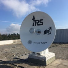
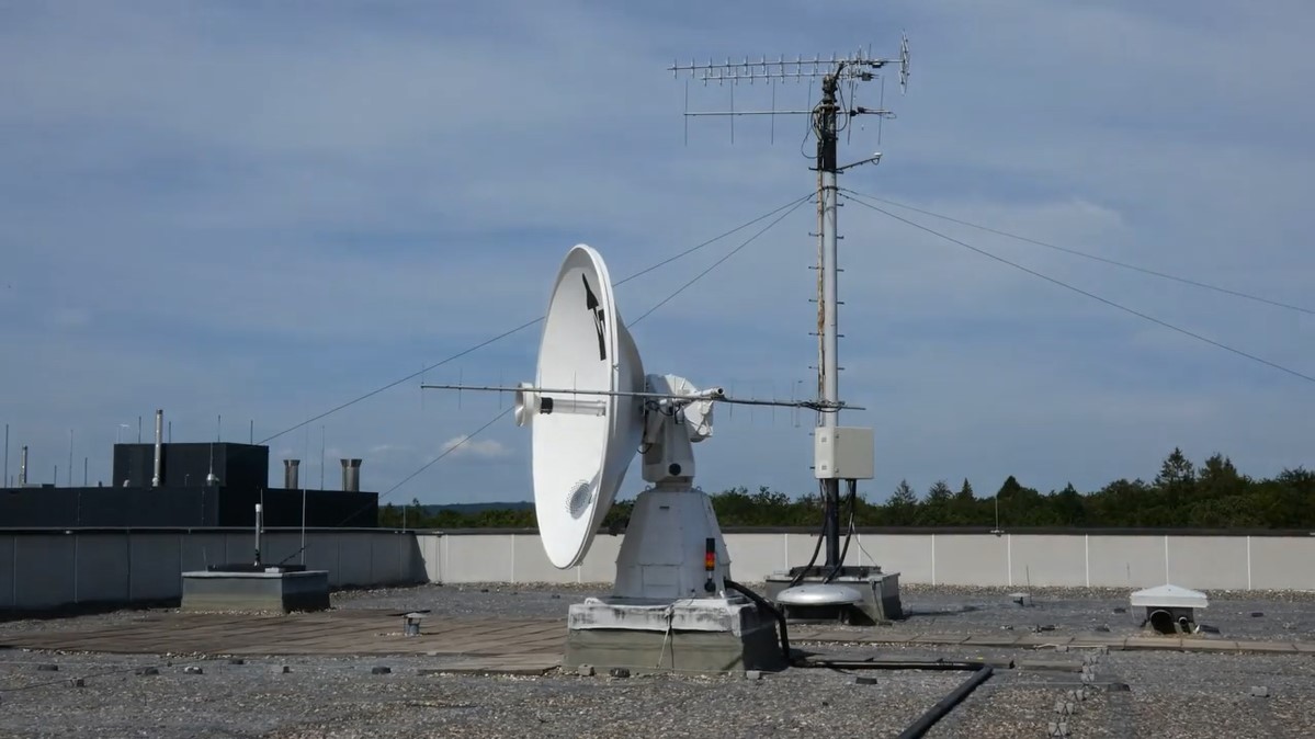
The antenna system is capable of transmitting within the commercial space research S-band (2075 MHz - 2090 MHz) with an equivalent output power of up to 20 kW (EIRP 43 dBW) and simultaneously, also within the commercial space research S-band (2257 MHz - 2278 MHz) to receive telemetry. Both are done in the right-hand circular polarization oriented (RHCP). Simultaneously, the antenna system is able to receive the payload data in the left-hand circular polarization LHCP with up to 10 Mbit/s in the amateur radio S-band (2400 MHz - 2428 MHz). We are using a parabolic antenna with a reflector diameter of 2.5 m (max. 34 dBi gain) which is mounted on a former radar rotor. To meet the requirements of the pointing accuracy, the antenna has been equipped with new stepper motors, position sensors and new control electronics. Overall, the antenna reaches a calibrated pointing accuracy of 0.3 ° at a maximum rotation speed of 12 °/s. An overview of the antenna system can be seen in the following picture. The location of the antenna system is on the roof of Pfaffenwaldring 31, with coordinates 48° 44' 58,19"N, 9° 06’ 13,84"E, about 442 m above N.N., QTH Locator JN48NR. This site provides good reception conditions due to its exposed location. For personal protection, an optoacoustic warning system has been installed, which signals movements of the reflector as well as the activation of the high power amplifier. For additional monitoring of rotor movement, a webcam is installed on the roof. Hence, the necessary safety equipment is installed to allow for a remote operation, which is controlled from the control room in RZBW (Pfaffenwaldring 29).
The high-quality LNAs, filters and power amps were purchased from SSB and Kuhne Electronic. Reception and transmission are taking place at an intermediate frequency of 70 MHz, so up and down converters towards the carrier frequencies are used. The transceiver is the commercial satellite transceiver CORTEX CRT of Zodiac Aerospace. To receive the payload data (DDS), a second channel of the base band modem is used. Furthermore, an in-house developed FPGA-based board can be used. In order to reduce costs for other radio HAMs, we are right now developing another solution based on a software-defined radio (SDR) transceiver.
As the central control software for the remote operation, the self-developed software "METEOR" is used. This has its own module for orbit prediction, is able to control all peripherals and measuring devices remotely, and regulates the other hand, the antenna pointing. It consists of a server part (CORE), which is running on a control computer in the shack room (next to the antenna on the roof), and a graphical user interface that connects via TCP/IP protocol with it. Via fiber-optic cables, this software is executed in the control center.
Flight Software Laboratory
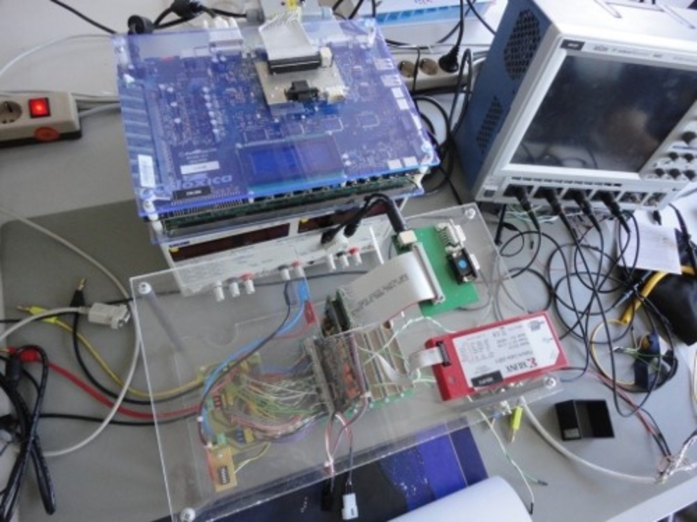
The development of flight software (FSW) is a significantly large part of spacecraft development. Consequently, the Institute of Space Systems has a dedicated FSW laboratory. Within the lab, IRS designs and tests modern concepts for the development of FSW. Currently, the team implements and tests the C++ and component-based "Flight Software Framework (FSFW)" and the control software for Flying Laptop. In addition, the team plan on-board computers and spacecraft avionics. In addition to a number of development computers, the lab also contains some development boards to allow on-target testing of software with little effort. For more complex tests, it is advantageous to have the simulation laboratory next door. The FSW laboratory is located in room 2.16 of the Space Center Baden-Wuerttemberg (RZBW).
Reinraum
In order to allow the implementation of the comprehensive development and verification activities within a small satellite project, a new clean room was established in the RZBW. It is designed to provide the required infrastructure and equipment for current and future small satellite projects. The satellite integration room meets industrial cleanliness and safety standards.
Characteristics:
- Provides a minimum cleanliness class of ISO 8 or class 100.000 (US FED STD 209E)
- Flow Boxes for high-level cleanliness of ISO 5 or class 100 (US FED STD 209E)
- Air parameters are constantly monitored
Ground Support Equipment:
- Omnidirectional integration wheel
- Crane
- Damped Optical work benches
- Several optical equipment like spectrometer, QHT lamp, integration sphere etc.
- Soldering work station for Printed Circuit Board manufacturing
- Comprehensive safety measures regarding Electrostatic Discharge
Layout:
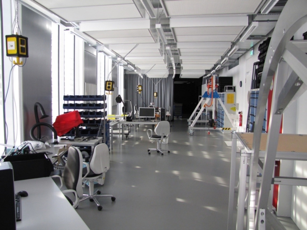
The entrance to the clean room is only accessible through a Preparation Room for cleanliness control. The Satellite Integration Room behind the Preparation Room extends to 119.5m².
This area is divided into three sections:
- Integration Area for satellite integration
- Functional Verification Area for component and satellite testing
- Optics Laboratory for development and calibration of optical instruments
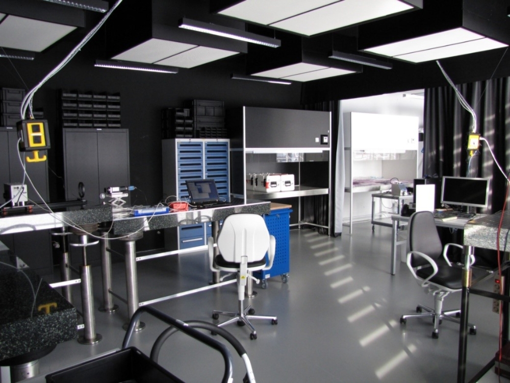
Optics laboratory
The Optics Laboratory is located in the integration room but is separated from the rest of the room by black curtains. In addition, its walls, ceiling and furniture are painted black to suppress stray light. The measuring equipment enables the team to determine the optical properties of the camera systems of Flying Laptop and to calibrate them.
The calibration of cameras can be classified into three categories:
- radiometric calibration,
- spectral calibration,
- Geometric calibration.
Radiometric calibration is used to measure the sensitivity of every pixel of the camera sensor. This makes it possible to determine the physical value of a signal by using the digital value measured by the camera. Therefore, the team uses a light source with known radiance and spectral distribution, a so-called integrating sphere, with a 500 mm diameter. The intention of spectral calibration is to investigate the sensor’s reaction to light at different wavelengths. This is important because CCD-Sensors as well as the optics have wavelength-dependent properties. To achieve this, the measurement setup consists of a Quartz Tungsten Halogen lamp as light source, a monochromator to select a narrow band of wavelengths from the light source spectrum, and a lens setup to focus the light. The primary purpose of geometric calibration is to determine the geometric distortions of the camera, so that the effect can be removed during post processing.
Satellite operating system
To operate a satellite in orbit the mentioned radio hardware is not sufficient. An additional ground control operating system is needed, which receivers, controls and encodes the commands for the satellite, as well as decoding and interpreting the satellites' telemetry. This is done in a new way compared to other universities. The IRS uses the satellite operation system SCOS-2000, which was developed by ESA and is used by industry. In combination with the CCSDS - radio protocol and the ESA Packet Utilization Standard (PUS) the IRS missions are succeeding the common European satellite industry standard. The trained students receive an unprecedented insight into the software, structures and problems, which they will encounter in their working life. This will give them an advantage compared to other universities.
To automate the satellite control the software MOIS, developed by Rhea System is used. This software makes it possible to run predefined procedures automatically to control SCOS-2000.
To rehearse the operation of the satellites and to test the hardware and software of the ground station functionally at an early stage, the EADS-Astrium developed simulator, which is also used for system simulation, will be used. Therewith the operational procedures can be verified and with the assistance of a relay satellite, the transmission path can be tested before the launch of the satellites.
Another tool to improve the satellite operation was developed at the institute for 3D visualization of the satellite in orbit. It is based on the open source software Celestia, in which a 3D model of the satellite is loaded into. During operation received telemetry data, e.g. attitude information can be visualized easily to get a direct impression of the current attitude of the satellite. Another planned feature is to overlay the current field of view of the cameras as well as the subsequent processing of telemetry data.
System Simulation and Verification
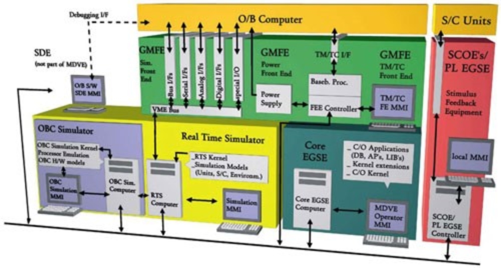
A spacecraft simulation environment with a complete command chain has been established at the Institute of Space Systems. It consists of an on-board computer, various development boards, a real-time spacecraft simulator, a mission control system and a flight/test-procedure execution engine. Furthermore, a 3D visualization facility is included. The small satellite FLP is the first satellite simulated in this environment, which enables control algorithms and on-board software testing before spacecraft hardware is available. In addition, hardware-in-the-loop tests are performed with the set-up. The elements of this command chain are all applied industrial systems, provided by market-leading companies. Both students and industrial partners benefit from this cooperation. Students are trained to use real industrial tools that they will use later in their careers and space industry gains improved access to qualified graduates. The illustration outlines the general architecture of the type of infrastructure used.
The real-time simulator is the heart of this environment and has been sponsored by Airbus DS. The on-board software is tested on either an FPGA development board or an engineering model of the real on-board computer. Both the simulator and the on-board software on the development board can be commanded by an ESA mission control system, SCOS-2000. This type of system will later be used in the ground station of the institute to command the satellite in orbit. Spacecraft test and later flight procedures can be edited and automatically executed by means of the procedure execution engine MOIS. This system has been provided by Rhea and enables test automation. Finally, the spacecraft is visualized as a 3D object representing its current simulated flight conditions. The open-source software Celestia is used for this purpose.
Tests showed that the spacecraft simulation environment turns out to be very precise compared to similar implementations in Matlab. Thesis topics regarding real-time simulation and software verifiaction are available.
System Simulation Software
- Aonix Ameos
-
All equipment models are written in C++ in the system simulation. Because all models share a common framework, a code generator is used to create raw code. In order to generate equipment-specific variables and methods, too, they are defined in UML class diagrams, which are also involved in code generation. The UML class diagrams can be created and edited with the software Ameos that is provided by Aonix.
- Eclipse Galileo
-
The C++ source files created with the code generator can be edited using the integrated development environment Eclipse Galileo. They are filled with algorithms, which model the functional performance of the equipment. Eclipse is a comfortable application for developing, compiling, debugging and displaying source code. It provides a graphical user interface and allows version management with CVS and SVN, which is applied in the software development.
- SCOS-2000
-
SCOS-2000 is applied to command the simulator and the connected on-board software. It allows comfortable live displays of telemetry during a simulation run. This mission control system was developed by ESA. It will also be applied in order to command the real satellite in space. SCOS-2000 can be connected both to the simulator and to the connected on-board software via an in-house developed Proxy process.
http://www.egos.esa.int/portal/egos-web/products/MCS/SCOS2000/
- MOIS
-
For automated operation of the mission control system the software MOIS (Manufacturing and Operations Information System) developed by Rhea is applied. It enables the creation of a procedure logic and its completion with telecommands and telemetry imported from SCOS-2000. The test procedures can also be executed with MOIS. As MOIS also allows responding to telemetry, it can replace the operator during simulation runs.
- Celestia
-
In order to depict position and attitude of the simulated satellite not only with graphs created in SCOS-2000, the 3D software Celestia is used. By converting the corresponding CATIA model and importing it into Celestia the satellite can be displayed in its simulated attitude and position. This is enabled by supplying Celestia with specific parameters of the simulator. By this means, the application allows a live 3D visualization.
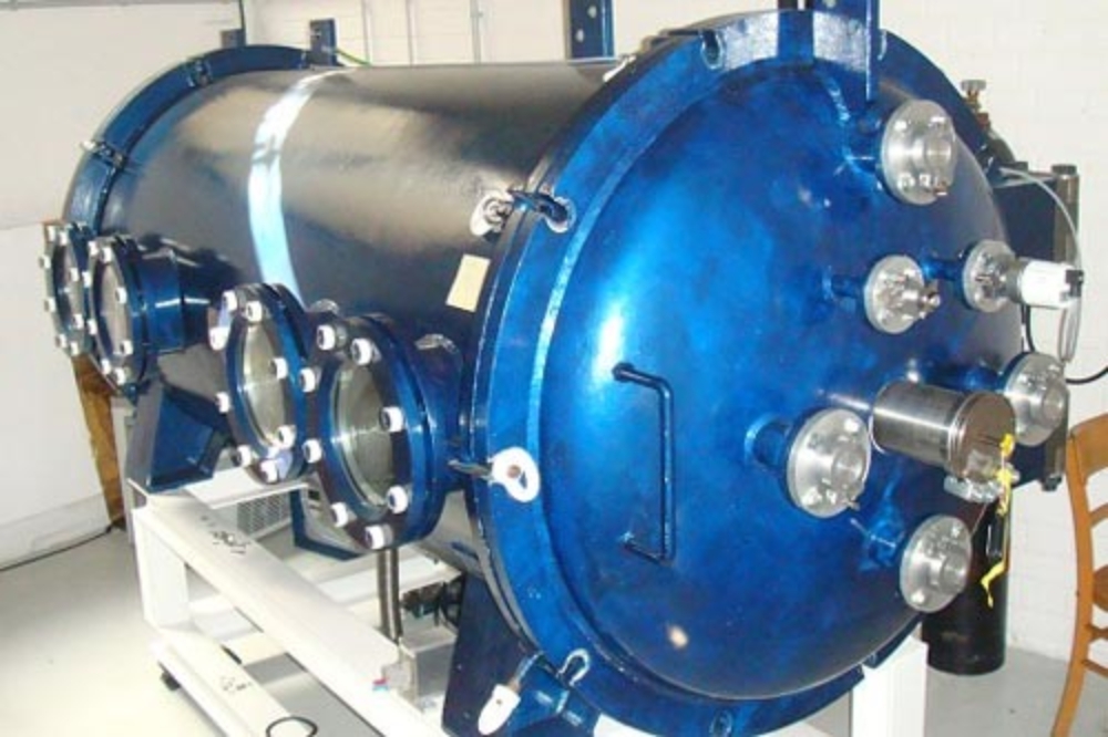
Thermal-Vacuum-Chamber
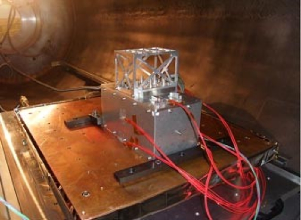
The Institute of Space Systems has a vacuum chamber that is exclusively used for thermal-vacuum tests of satellite components. By means of the absence of convection, it is possible to simulate the conditions for satellite systems as they would be in Earth orbit. The low pressure in the chamber is generated by two different pumps. At first, a vane pump establishes a prevacuum, which is needed for the turbo pump. During the tests, the satellite components are exposed to different temperatures while monitioring their functionality. This is mandatory since the temperature in a satellite can vary more than 100 K. The temperature of the components can be adjusted by a circulator, which pumps silicon oil through a copper plate and thus cools or heats the plate. Measurements from temperature sensors, which are located on different areas of the component, can be compared with mathematical predictions. The image below shows a component populated with temperature sensors (red) during a test in the thermal-vacuum-chamber.
The specifications of the thermal-vacuum-chamber as an overview:
|
Diameter |
1 m |
|
Length |
2 m |
|
Temperature range |
-40°C to 115°C |
|
Cooling plate |
400 x 500 mm² (effective 350 x 400 mm²) |

Sabine Klinkner
Prof. Dr.-Ing.Professor of satellite technology, Deputy Director