The Flying Laptop has a total of seven systems that keep the small satellite running. These systems are the on-board computer, on-board software, power supply, communications, attitude control, structure and mechanisms, and thermal control.
On-Board Computer
For computation and calculation processes aboard the Flying Laptop, an On-Board Computer (OBC) system is necessary. As the Flying Laptop will be exposed to the environmental conditions existing in space, it needs to be robust against radiation and a wide range of temperature. Therefore an already existing processor, that has been validated to work under the mentioned conditions, has been chosen to be the core of the OBC system. The UT699 is based on the already flown LEON3FT processor family developed by ESA/ESTEC. This processor as well as the processor-close memory parts are placed on the OBC core board. This core board is designed and delivered by Aeroflex Colorado Springs, USA.
The OBC executes the Attitude Control System (ACS) algorithms, Thermal Control System (TCS) algorithms, controls the dedicated payload computer and is in charge of housekeeping observation and Failure Detection, Isolation and Recovery (FDIR). Housekeeping data will be collected and transmitted to the ground station if requested.
As the processor board of the OBC system has only a SpaceWire-Interface to send and receive data, an interface board, or I/O-Board, is placed between the core board and the subsystems of the Flying Laptop. This board is equipped with SpaceWire interfaces on one side and the according interfaces to the particular subsystems on the other side, for example LVDS or I²C. The I/O-Board does not include any intelligence but only transmits data when a Read or Write command is sent by the on-board software. Also on the I/O-Board, there are memory chips to allow buffering of telemetry data. The I/O-Board is designed and delivered by 4Links, U.K.
For the communication to the ground station, a dedicated board with a CCSDS-Chip implementation is also part of the OBC system. This chip handles the data link layer of the CCSDS satellite communication protocol. Using this protocol ensures compatibility to many ground stations, for example, those from space agencies like ESA. The board is designed and delivered by 4Links and is loaded with a CCSDS-Chip-implementation by Aeroflex Gaisler, Sweden. The CCSDS-Board will also be connected to the OBC via SpaceWire interface.
All boards are available in duplex design. This allows switching between devices to gain redundancy and compensation of malfunctions. Except for the communication boards, all boards are used in cold redundancy.
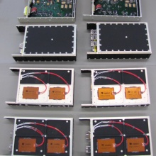
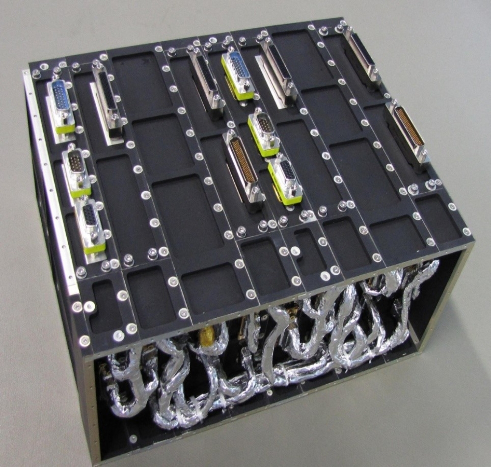
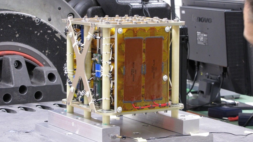
Due to the unregulated voltage bus aboard the Flying Laptop, there are two identical power boards, which produce the required small voltage levels. In total there are eight boards comprising the FLP OBC system, as shown in the above picture.
The eight boards are are conncted via an especially designed micro-harness. This can be seen in the picture at the top. Regarding the significantly small space available for this internal harness, specialists from HEMA Kabeltechnik have been doing the design and manufacturing.
On the back of every second board, there are emergency heaters. These will be activated by the PCDU in case the temperature in the system drops below a certain limit. This heater system has also been installed in duplex design.
On-Board Software
The On-Board Software of a satellite needs to offer the following functions:
- Telecommands can be received and executed
- Telemetry is generated depending on state and events
- Sensors and Actuators can be read and commanded
- Controller algorithms can be executed
- Faults must be detected and isolated
The software development for the Flying Laptop is done completely at the Institute of Space Systems (IRS). This permits students to directly participate in the development process.
The On-Board Software of the Flying Laptop uses RTEMS as base and is written completely in C++. The telecommanding and monitoring of the systems implements the ECSS PUS standard. An open mode concept not only allows the definition of system modes but also commanding single components into modes independently of each other.
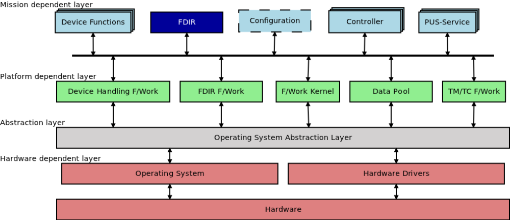
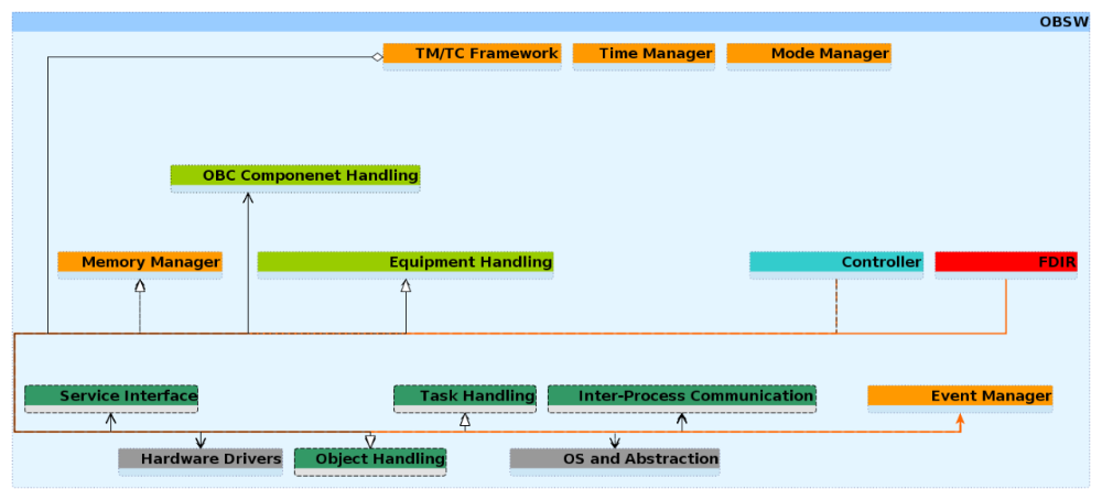
The software is built from different layers and components:
The layers support hardware abstraction and reusability. The hardware layer accesses hardware directly while the higher layers offer abstract functions. The so-called platform layer pursues the idea to build a framework that can be adapted to other satellite applications. The mission layer is built on the platform layer and contains all the functions specialized to the Flying Laptop mission.
Power Supply
The electrical power supply of the Flying Laptop is facilitated by three solar panels, which were manufactured by Airbus Defence and Space. One solar panel is body mounted, two are deployed once the satellite is launched and separated from the launcher. The bus voltage is unregulated between 19V and 26V. DC/DC converters dedicated to every unit obtain the necessary voltage for every component.
The Power Control and Distribution Unit (PCDU) was manufactured by Vectronic Aerospace. It detects the launcher separation, controls the power distribution to the components and adjusts the charging of the battery. Beyond these default operations, the PCDU executes further tasks. The PCDU collects data, currents and voltages of a majority of the satellite´s sensors and forwards them to the On-Board Computer (OBC) for further processing. Together with the OBC system, the PCDU is one of the central controlling units, which can switch over to the redundant unit branch in case of an emergency. In particular, the PCDU can activate the available redundant units in case there is a breakdown of the OBC. The PCDU features dedicated input interfaces for High Priority Commands (HPCs). The HPCs are decoded and sent to the PCDU without involving the OBC. Thus, essential telecommands can be received and executed by the PCDU, fulfilling its purpose as a backup system.
As a secondary power source, the FLP is equipped with a battery (see image). It consists of three independent battery strings made of Lithiumironphosphate cells manufactured by A123 Systems (type ANR26650M1-B). Each of these strings is directly connected to one of the solar panels. As the middle body mounted solar panel generates less power than the wing panels, the battery string for this panel consists of 28 cells, whereas the strings for the wing panels consist of 35 cells each. In total, a voltage of 19V to 26V is yielded at a total capacity of all strings combined of roughly 700Wh. Additional circuitry is used to balance the cell voltages and to send a signal to stop charging to the PCDU if the voltage of one cell reaches the maximum allowed value. The battery is used to supply power to the satellite system during eclipse and to provide additional energy during manoeuvres in which the power consumption of the system exceeds the power generated by the solar panels.

Communication
In satellite communication systems, two systems with different functions are commonly distinguished: The Telemetry, Tracking and Control (TT&C) System and the Payload Data Downlink System. The TT&C system is used to transmit housekeeping data, to receive commands and to determine the position and the orbit of the satellite. It has to perform with a high reliability, but the necessary data rates are not that high. Typical data rates are a few kbit/s for the uplink (ground station -> satellite) and about 100kbit/s for the downlink (satellite -> ground station). Sometimes it is also referred as the TM/TC system, if no tracking is used. The Payload Data Downlink System, on the other hand, is used exclusively to transmit payload data. Unlike TT&C and TM/TC system, the required reliability is lower as the required data rates are much higher.
TM/TC-System of the Flying Laptop
The TMTC system of the Flying Laptop is a highly reliable commercial system operating on commercial S-Band frequencies (between 2.0 GHz and 2.3 GHz) at a data rate of 128 kbit/s for the TM downlink and 4 kbit/s for the TC uplink. In order to improve the reliability, both the receiver and the transmitter are built redundantly so that the TMTC system is still fully functional in case one unit fails. The FLP is equipped with two hemispherical turnstile antennas for the TM/TC system so that telemetry can be sent and telecommands can be received at all times, regardless of the attitude of the satellite.
|
|
Downlink |
Uplink |
Antennas |
|
Frequency |
2263.5 MHz |
2083.5 MHz |
|
|
Bandwidth |
350 kHz |
8 kHz |
|
|
Data rate (net) |
56 kbps |
4 kbps |
|
|
Modulation |
BPSK (NRZ-L) |
PM (16 kHz BPSK sub-carrier) |
|
|
Coding |
CCSDS (Conv. R=1/2, K=7 & R.S. 255/223) |
CCSDS (BCH) |
|
|
Sensitivity / Output power |
-118 dBm |
28 dBm |
|
|
Required Eb/N0 |
4.5 dB |
13.5 dB |
|
|
Polarization |
|
|
RHCP |
|
Max. directivity |
|
|
5 dBi |
|
Theta3dB angle |
|
|
110 deg |
Payload Data Downlink System
The payload Data Downlink System (DDS) is used to downlink payload data, especially larger amounts of image data generated by the cameras of the Flying Laptop (MICS / PAMCAM) to a ground station. The Flying Laptop DDS uses data rates of up to 10Mbit/s. Because the available space and the electrical power are limited, a directional horn antenna is used, which has a much higher gain in boresight than the TT&C rod antennas for example. Due to the antenna’s directivity, its boresight needs to be directed to a receiving ground station in order to transmit data to the ground.
The DDS is designed to operate on ham radio S-Band frequencies between 2.4 GHz and 2.45 GHz. It receives the data it shall transmit to the ground as well as the clock signal from the Payload On-Board Computer (PLOC). The whole system is being developed at the IRS.
|
|
DDS Downlink |
Antenna |
|
Frequency |
2408.0 MHz |
|
|
Bandwidth |
10 MHz |
|
|
Data rate (net) |
5.5 Mbps |
|
|
Modulation |
QPSK (NRZ-L, SRRC α=0.4) |
|
|
Coding |
CCSDS (R.S. 255/223 & Pseudo-Random.) |
|
|
Output power |
30 dBm |
|
|
Required Eb/N0 |
7.8 dB |
|
|
Polarization |
|
LHCP |
|
Max. directivity |
|
13.5 dBi |
|
Theta3dB angle |
|
15 deg |
Attitude Control
The satellite is 3-axis stabilized by actuators, which consist of reaction wheels and magnetic torquers.
The four reaction wheels are aligned in a tetrahedron configuration to ensure redundancy. This makes it possible to compensate for the loss of one of the four reaction wheels. The magnetic torquers (torque rods) are mainly used to dump the momentum accumulated by the reaction wheels over time. They are also used during the LEOP phase (Launch and early operation phase) to stabilize the satellite after the separation from the launch vehicle, because all higher systems (e.g. reaction wheels) are turned off during that phase.
Five different types of sensors monitor the attitude motion:
- two 3-axis magnetometers
- a 4π coarse sun sensors system
- four Fiber Optic Gyros as rate sensors
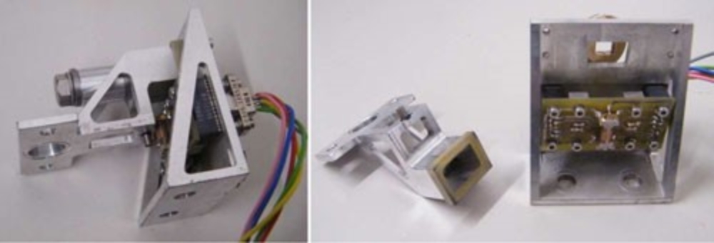
- a star tracker unit with two camera heads
- three GPS Receivers
The Zarm AMR-magnetometer uses a magneto-resistive sensor and has a digital interface. For the measurement of the angular velocity, four fiber optical rate sensors will be used. A star tracker, the micro Advanced Stellar Compass (µASC), from the Technical University of Denmark will provide a relative pointing knowledge of up to two arcseconds. When the satellite is stabilized and rotates with a slew rate of less than 1.2 °/s the star tracker delivers regular attitude updates. To provide full accuracy about all axes and to decrease the probability of blinding during maneuvers, a second camera head unit is mounted on the satellite with its optical axis tilted away from the first one. To support accurate target pointing of the spacecraft during imaging and ground station contacts, the satellite will be equipped with a GPS navigation system consisting of three Phoenix receivers from DLR/GSOC.
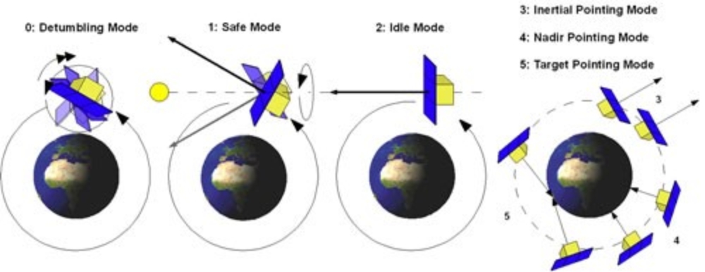
The attitude control system can command a total of five attitude control modes, each specifically designed for a certain operational mode or emergency condition.
- The Detumbling Mode (Mode 0) is used after launcher separation or if the satellites body rates, exceed 3 °/s and is initiated automatically. The Flying Laptop measures its rotational velocity with the magnetometers and uses the magnetic torquers to slow the rotation down.
- The Safe Mode (Mode 1) is initiated by the ground station or the automatic fault detection system in case of a mission critical error or failure. To stabilize the satellite and to ensure the solar panels are pointing towards the sun and the battery gets charged, the controller uses the sun sensors to orient the satellite's principle axis towards the sun and the magnetometers and magnetic torquers are used to initiate a 2 °/s spin about this axis. This ensures a stable attitude, which is also robust against disturbances.
- If the satellite is operational but is unused it is commanded to the Idle Mode (Mode 3). During the Idle Mode the solar panels are actively pointed to the sun using the reaction wheels, the fiber optical gyros, the sun sensors and the star trackers. The batteries will be charged most efficiently that way and the satellite is ready to carry out observations in the pointing modes immediately.
- For image acquisition, three different attitude control modes are defined and shown above: Inertial Pointing Mode (Mode 3), Nadir Pointing Mode (Mode 4) and Target Pointing Mode (Mode 5).
In the target pointing, also known as spotlight mode, the satellite points to a fixed spot on the surface of the earth during a fly-over. The slew rate for this maneuver is 1 °/s (max.) and follows a non-linear bell-shaped curve over time. This is the most demanding mode of the satellite in terms of control algorithms and accuracy.
In the Nadir Pointing Mode the payload, cameras are pointed "directly down" (towards nadir) and in the Inertial Pointing Mode, the Cameras (or any side of the satellite) can be pointed to a celestial object like stars, the sun or the moon. In this mode the Flying Laptop is not rotating; it is inertially fixed in its attitude.
The startrackers, the fiber optical gyros, the GPS and the reaction wheels are used in the pointing modes. Optionally the magnetometers and the torquers can be switched on to desaturate the reaction wheels.
The attitude control system needs to provide the selected earth observation instruments with a high pointing knowledge of 2.5 arc seconds and a pointing accuracy of 150 arc seconds as well as agile maneuvering capabilities, which is a big challenge for a micro-satellite. This can only be achieved by a thorough control concept and high performance sensors/actuators.
New methods in implementing the attitude control algorithms are presently being pursued.
Main structure
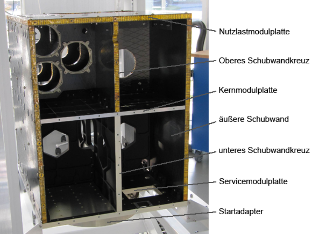
The main structure of the Flying Laptop is designed to be a hybrid structure. The lower part consists of integral aluminium parts and therefore offers a cost-effective and precise assembly, adjusted force transmission and good thermal properties. The upper part, where the optical systems are installed, consists of carbon-fiber reinforced sandwich structures. These offer a low mass, high stiffness as well as low thermal longitudinal expansion to provide a stable calibrated alignment of the cameras in the satellite and to each other.
The satellite is divided into three segments. The launch adapter is attached to the lowest module, the service module, in which the so-called service components like on-board computer, the battery and the power control and distribution unit are located. The second module, the core module, is located in the middle of the satellite and houses systems components like reaction wheels, the components of the data downlink system and the fiber optical gyros. The payload module forms the upper segment of the satellite main structure. In this module, the panoramic camera, the optical link OSIRIS as well as both of the optical benches containing the optical camera system, MICS and the camera heads of the star trackers are located. To ensure the proper alignment of the camera systems to each other sandwich structures are used in the payload module.
The three segments are connect by a shear wall crossing and two outer shear walls. The shear wall crossing between service and core module consists also of integral aluminium parts. All other shear walls consist of sandwich structures to reduce the effects of thermal deformation on the payload module as far as possible. The sandwich and aluminium components are connected with full floating fasteners, which compensate the occurring inner tension caused by different thermal expansion coefficients.
Deployment mechanism
Due to the high-energy consumption and the limited integration volume in the launcher, the Flying Laptop features two deployable solar panels, which need to be retracted during the launch. After successful separation those panels will be deployed and form a plane with the body-mounted center solar panel. The deployment will be accomplished by a newly developed mechanism consisting of two hinges and two binders per panel. The holding-down clamp features a melting wire mechanism is used and an escapement. The bolts retaining the solar panels during the launch are attached to the satellite using a split pod. A melting wire holds this pod together during launch. For deployment, the wire is melt via a heat resistor, releasing the split pod. The bolt is pulled out of the pod by a compression spring, so that the prestressed hinges unfold the solar panels. The hinges are partly designed as fixed joints and partly as plunging joints and they are prestressed by leg springs. A damper absorbs the rotation energy during the deployment so that transient oscillation is suppressed. After deployment, the panels are held in place by the pretension of the mechanisms' leg springs. By using ball joints, the hinge mechanism can compensate axis aberrations up to 1°. The entire deployment mechanism has a mass of under 2 kg and a power consumption of 64 W for approx. 30 seconds.
De-orbit mechanism
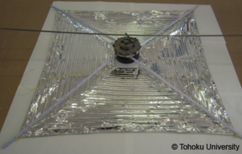
In 2002, the "Inter-Agency Space Debris Coordination Committee" of the United Nations adopted a code of conduct on the prevention of space debris. It states that the owners of object in the low earth orbit have to ensure, that their object will reenter in the Earth's atmosphere within 25 years after its lifetime. This prevention of space debris reduces the risk of collisions between objects in low Earth orbit. In order to adhere to the UN regulation, the FLP will carry a de-orbiting mechanism. The satellite system will deploy a 2.5 x 2.5 m² plain foil, which increases the aerodynamic drag of the satellite in the residual atmosphere. Thus, the orbit height will decrease rapidly. The size of the foil is designed in a way that the Flying Laptop reenters into Earth's atmosphere within 25 years and will burned up there.
The de-orbit mechanism is a purchase part and was developed in a cooperation of Tohoku University, Japan and the company Nakaschimada Engineering Works Ltd.
Thermal Control
The absence of a dense atmosphere in an Earth orbit eliminates the natural heat transfer though convection between the satellite and its environment. Therefore, temperatures ranging from -100°C to +150°C are possible, whereas the electronics in satellites are only certified for operation between -20°C and +80°C.Outside of this temperature range, it is likely that electronical connections on circuit boards will break or melt. The objective of the thermal control system is to keep the temperature of the satellite and its components within the allowed temperature ranges. The thermal control system consists of several elements such as temperature sensors and elements that influence the temperature on the satellite. The temperature inside the satellite is measured via Pt1000 platinum temperature sensors. These sensors increase their electric resistance during rising temperatures and this resistance can be measured. Pt-elements provide a better average accuracy over the entire possible temperature range of the satellite compared to other temperature sensors and they do not require measuring amplifiers.
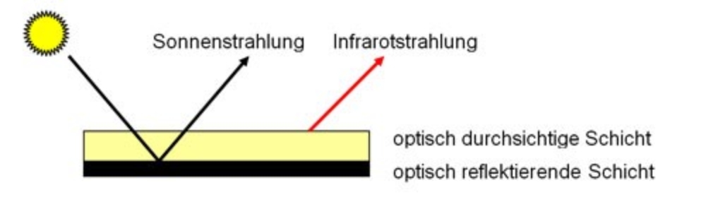
In order to influence the temperature with passive means, the main body of the satellite is covered mostly with MLI (Multi Layer Insulation) to minimize the radiation exchange between the satellite and its environment. MLI consists of multiple stacked layers of film made of e.g. polyimides which are separate by fine synthetic meshes. By these means, each film layer decreases the absorption and emission of radiation by the satellite. On all surfaces not covered with MLI, so called SSMs (Second Surface Mirrors) will be applied, which serve as radiators emitting the satellite's heat in the form of infrared radiation while reflecting the sunlight.
The batteries and the star trackers are both equipped with appropriate radiators and are insulated from the rest of the satellite to ensure the narrow temperature ranges of these components. The satellite is also equipped with electrical heating films, which are activated in case the temperatures are too low. The on-board computer of the satellite primarily controls these heaters. In case of an on-board computer failure, the heating films are controlled by thermostats (bimetal-switches).

Sabine Klinkner
Prof. Dr.-Ing.Professor of satellite technology